Using an SD Card with a TRENTOS System
Overview
TRENTOS based systems that need to enable multiple client components to access a single storage device can do so by employing a StorageServer component.
As this server will statically assign a single “slice of storage” to every client connected to it, this partitioning of the storage device needs to be adapted to the SD card, to allow for interoperability between the operating system running on a PC and the embedded TRENTOS system on the board.
This chapter will demonstrate how an example partition table layout (either as MBR or GPT) can be created on an SD card and how the static configuration of a StorageServer component needs to be adapted to this layout so that files written to the different partitions on the SD card can be easily exchanged between the TRENTOS system and the PC.
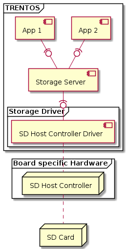
The guiding example system architecture for the setup steps outlined in this chapter is shown in the diagram below. In this TRENTOS system, the StorageServer component needs to manage two memory slices, each one individually mapped to one of the two connected clients.

Master Boot Record (MBR)
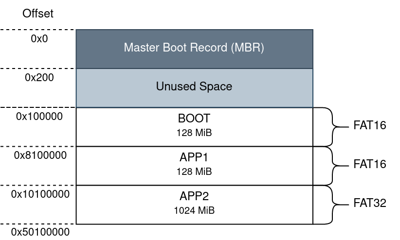
Derived from the architecture shown in the overview section above, a possible Master Boot Record (MBR) partition table layout for this example system could be structured as follows:

Info: The layout is 1 MiB aligned so even though the MBR itself only has a size of 512 Byte, the reserved space for this record is 1 MiB.
Setting up the illustrated layout can be done by utilizing a tool such
as parted. Any other tool that can create and manipulate partition
tables could also be used for this task. It is important to note that
throughout all the following steps, it will be assumed that the SD card
has the device path /dev/sda.
In order to be able to reformat the SD card, all existing partitions on it need to be unmounted in case they were automatically mounted once the card got connected to the PC.
umount /dev/sda?*
Once all the currently existing partitions of the SD card have been
successfully unmounted, it can be overwritten with the new partition
layout. Note that using sudo for some of the following commands
may not be required, this depends on your Linux group membership giving
your account access to the device path (in the current example
/dev/sda).
sudo parted --script /dev/sda mklabel msdos \
    mkpart primary 1MiB 129MiB \
    mkpart primary 129MiB 257MiB \
    mkpart primary 257MiB 1281MiB
This command will create an MBR formatted layout with the three entries for the “BOOT”, “APP1” and “APP2” partitions.
The created partitions will be formatted to FAT with a file system
formatting tool such as mkfs.vfat.
sudo bash -c 'mkfs.vfat -n "BOOT" /dev/sda1 \
    && mkfs.vfat -n "APP1" /dev/sda2 \
    && mkfs.vfat -n "APP2" /dev/sda3'
In case you a preparing the SD card to be used with the Raspberry Pi 3 Model B+ it is additionally required to set the LBA flag (0x0C = FAT32 with LBA) for the “BOOT” partition. Without this flag set, the board will not be able to boot from this partition.
sudo parted --script /dev/sda set 1 lba on
Remount all the partitions on the SD card (either by reinserting it into the PC or with the following command).
ls /dev/sda?* | xargs -n1 udisksctl mount -b
The SD card should now be partitioned into the created partitions and these partitions should be FAT formatted. This can be verified by running:
sudo parted /dev/sda u MiB print
If all steps succeed, the expected outcome should look similar to the following snapshot.
Model: Generic STORAGE DEVICE (scsi)
Disk /dev/sda: 30437MiB
Sector size (logical/physical): 512B/512B
Partition Table: msdos
Disk Flags:
Number  Start    End      Size     Type     File system  Flags
 1      1,00MiB  129MiB   128MiB   primary  fat16        lba
 2      129MiB   257MiB   128MiB   primary  fat16
 3      257MiB   1281MiB  1024MiB  primary  fat3
The SD card itself is now prepared with the partition table layout but the resulting partition size and offset configuration still need to be adapted for the configuration of the StorageServer component.
//-----------------------------------------------------------------------------
// StorageServer
//-----------------------------------------------------------------------------
// 129 MiB reserved for MBR and BOOT partition.
#define MBR_STORAGE_SIZE    (1*1024*1024)
#define BOOT_STORAGE_SIZE   (128*1024*1024)// 128 MiB for APP1
#define APP1_STORAGE_OFFSET (MBR_STORAGE_SIZE + BOOT_STORAGE_SIZE)
#define APP1_STORAGE_SIZE   (128*1024*1024)// 1024 MiB for APP2
#define APP2_STORAGE_OFFSET (APP1_STORAGE_OFFSET + APP1_STORAGE_SIZE)
#define APP2_STORAGE_SIZE   (1024*1024*1024)
With the presented setup in place, the pre-partitioned SD card can now be mounted on both, the TRENTOS system and the PC.
This described setup was tested on the Nitrogen6_SoloX, the BD-SL-i.MX6, and the Raspberry Pi 3 Model B+ using SD cards driven by the SdHostController component with applications accessing the different partitions on the SD card through the StorageServer component.
To get a better understanding of how this setup can be applied to a TRENTOS system, it is recommended to take a closer look at the IoT Demo App for i.MX6. This application makes use of an MBR partitioned SD card that is managed by a StorageServer component.
Creating an Extended Partition
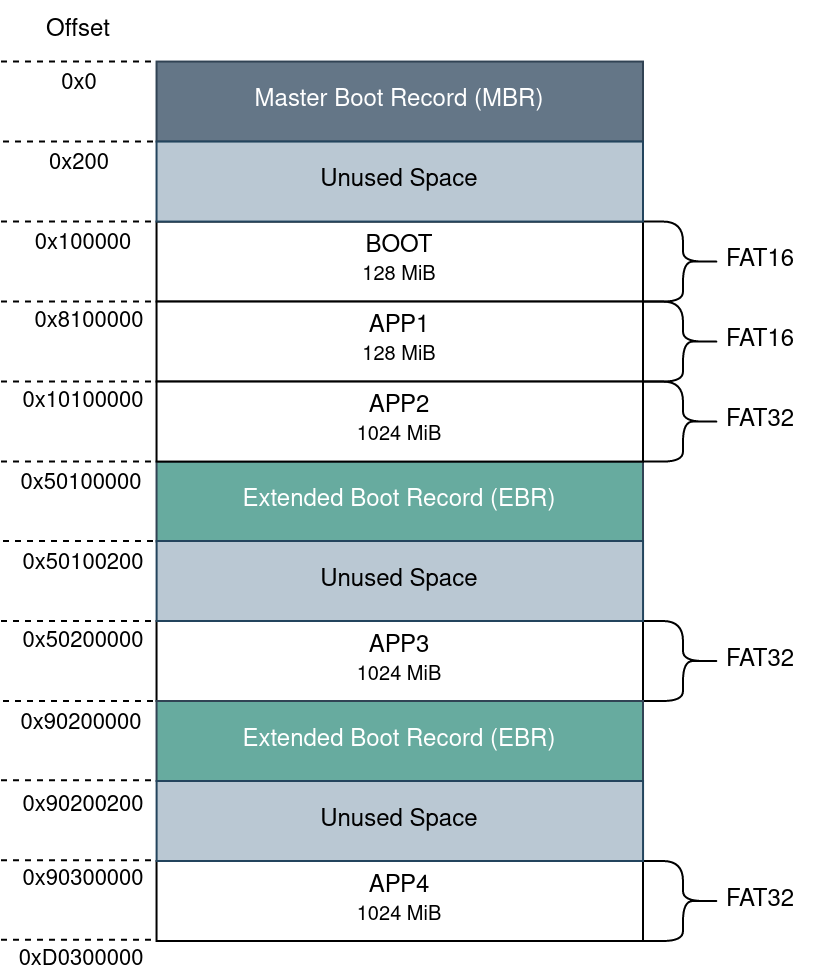
MBR has a clear limitation in that it only supports up to four primary partitions. If more partitions are required, it is necessary to designate one of the primary partitions as an “extended partition” which can then be subdivided into several logical partitions inside of it. The structure of this extended partition is described by one or more extended boot records (EBRs) located in the first sector of the extended partition.
Assuming two additional components will be connected to the StorageServer component and these also require dedicated memory slices (wrapped into partitions) to operate on, the initial partition table could be extended to the following layout.

Info: The layout is 1 MiB aligned so even though the MBR and EBRs only have a size of 512 Byte the reserved space for these records is 1 MiB, leaving some unused space in between. It is also important to note that the diagram simplifies the placement offsets of the EBRs, as the following EBRs after the initial EBR are not necessarily placed directly at the end of the preceding logical partition but rather within the reserved 1MiB range between the logical partitions. For further information, please refer to the EBR specification.
To extend the already created table to the variant shown above, it is necessary to first designate one of the four possible primary partitions as an extended partition followed by the creation of the two additional logical partitions for “APP3” and “APP4”. All the following steps are based on the assumption that the utilized SD card has already been partitioned with the MBR and the first three partitions for “BOOT”, “APP1”, and “APP2” as outlined in the previous section.\
sudo parted --script /dev/sda \
    mkpart extended 1281MiB 3331MiB \
    mkpart logical 1282MiB 2306MiB \
    mkpart logical 2307MiB 3331MiB
Both additional partitions will also be formatted to FAT. Note that we are skipping the fourth partition as this is the beginning of the extended partition that only contains the initial EBR which described how large the complete extended partition is and where the first logical partition and the next EBR are located.
sudo mkfs.vfat -n "APP3" /dev/sda5 \
    s&& sudo mkfs.vfat -n "APP4" /dev/sda6
Mount the additionally added partitions.
udisksctl mount -b /dev/sda5 \
    && udisksctl mount -b /dev/sda6
Verify that the extended partition containing the added logical partitions was created successfully by running:
sudo parted /dev/sda u MiB print
The expected outcome should look similar to the following snapshot.
Model: Generic STORAGE DEVICE (scsi)
Disk /dev/sda: 30437MiB
Sector size (logical/physical): 512B/512B
Partition Table: msdos
Disk Flags:
Number  Start    End      Size     Type      File system  Flags
 1      1,00MiB  129MiB   128MiB   primary   fat16
 2      129MiB   257MiB   128MiB   primary   fat16
 3      257MiB   1281MiB  1024MiB  primary   fat32
 4      1281MiB  3331MiB  2050MiB  extended               lba
 5      1282MiB  2306MiB  1024MiB  logical   fat32
 6      2307MiB  3331MiB  1024MiB  logical   fat32
The extended partition table also needs to be updated for the configuration of the StorageServer component of the example system.
//-----------------------------------------------------------------------------
// StorageServer
//-----------------------------------------------------------------------------
// 129 MiB reserved for MBR and BOOT partition.
#define MBR_STORAGE_SIZE    (1*1024*1024)
#define BOOT_STORAGE_SIZE   (128*1024*1024)// 128 MiB for APP1
#define APP1_STORAGE_OFFSET (MBR_STORAGE_SIZE + BOOT_STORAGE_SIZE)
#define APP1_STORAGE_SIZE   (128*1024*1024)// 1024 MiB for APP2
#define APP2_STORAGE_OFFSET (APP1_STORAGE_OFFSET + APP1_STORAGE_SIZE)
#define APP2_STORAGE_SIZE   (1024*1024*1024)// 1 MiB reserved for EBR in between
// the logical partitions of the extended partition.
#define EBR_STORAGE_SIZE    (1*1024*1024)// 1024 MiB for APP3
#define APP3_STORAGE_OFFSET (EBR_STORAGE_SIZE + APP2_STORAGE_OFFSET + APP2_STORAGE_SIZE)
#define APP3_STORAGE_SIZE   (1024*1024*1024)// 1024 MiB for APP4
#define APP4_STORAGE_OFFSET (EBR_STORAGE_SIZE + APP3_STORAGE_OFFSET + APP3_STORAGE_SIZE)
#define APP4_STORAGE_SIZE   (1024*1024*1024)
GUID Partition Table (GPT)
Warning: Using the GPT layout scheme with the Raspberry Pi 3 Model B+ will result in an inability to boot as the board expects an SD card with an MBR partition table layout. If you are preparing an SD card for this platform it is advised to follow the steps outlined above on how to correctly partition a storage device with an MBR layout.
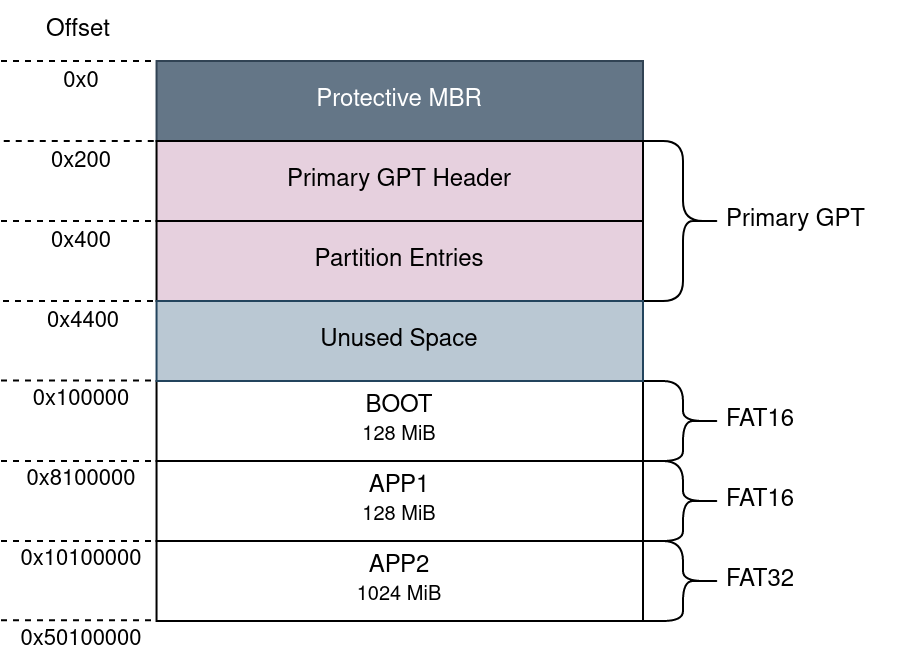
Compared to the MBR partition table layout, the GUID Partition Table (GPT) additionally includes the primary GPT, which can be subdivided into the primary GPT header and the partition entries. Based on the system architecture shown in the overview section the following GPT layout example will be used as the guideline for all setup steps.

Setting up the partition table layout can be done by utilizing a tool
such as parted. Any other tool that can create and manipulate
partition tables could also be used for this task. It is important to
note that throughout all the following steps, it will be assumed that
the SD card has the device path /dev/sda.
In order to be able to reformat the SD card, all existing partitions on it need to be unmounted in case they were automatically mounted once the card got connected to the PC.
umount /dev/sda?*
Once all the currently existing partitions of the SD card have been
successfully unmounted, it can be overwritten with the shown partition
layout. Note that using sudo for some of the following commands
may not be required, this depends on your Linux group membership giving
your account access to the device path (in the current example
/dev/sda).
sudo parted --script /dev/sda mklabel gpt \
    mkpart primary 1MiB 129MiB name 1 "BOOT" \
    mkpart primary 129MiB 257MiB name 2 "APP1" \
    mkpart primary 257MiB 1281MiB name 3 "APP2"
This will create a GPT formatted layout with the three entries for the “BOOT”, “APP1” and “APP2” partitions.
The created partitions will be formatted to FAT with a file system
formatting tool such as mkfs.vfat.
sudo bash -c 'mkfs.vfat -n "BOOT" /dev/sda1 \
    && mkfs.vfat -n "APP1" /dev/sda2 \
    && mkfs.vfat -n "APP2" /dev/sda3'
Remount all the partitions on the SD card (either by reinserting it into the PC or with the following command).
ls /dev/sda?* | xargs -n1 udisksctl mount -b
The SD card should now be partitioned into the created partitions and these partitions should be FAT formatted. This can be verified by running:
sudo parted /dev/sda u MiB print
If all steps succeed, the expected outcome should look similar to the following snapshot.
Model: Generic STORAGE DEVICE (scsi)
Disk /dev/sda: 30437MiB
Sector size (logical/physical): 512B/512B
Partition Table: gpt
Disk Flags:
Number  Start    End      Size     File system  Name   Flags
 1      1,00MiB  129MiB   128MiB   fat16        BOOT
 2      129MiB   257MiB   128MiB   fat16        APP1
 3      257MiB   1281MiB  1024MiB  fat32        APP2
The SD card itself is now prepared with the partition table layout but the resulting partition size and offset configuration still need to be adapted for the configuration of the StorageServer component.
//-----------------------------------------------------------------------------
// StorageServer
//-----------------------------------------------------------------------------
// 129 MiB reserved for GPT and BOOT partition.
#define GPT_STORAGE_SIZE    (1*1024*1024)
#define BOOT_STORAGE_SIZE   (128*1024*1024) // 128 MiB for APP1
#define APP1_STORAGE_OFFSET (GPT_STORAGE_SIZE + BOOT_STORAGE_SIZE)
#define APP1_STORAGE_SIZE   (128*1024*1024) // 1024 MiB for APP2
#define APP2_STORAGE_OFFSET (APP1_STORAGE_OFFSET + APP1_STORAGE_SIZE)
#define APP2_STORAGE_SIZE   (1024*1024*1024)
With the presented setup in place, the pre-partitioned SD card can now be mounted on both, the TRENTOS system and the PC.
This described setup was tested on the Nitrogen6_SoloX and the BD-SL-i.MX6 using SD cards driven by the SdHostController component with applications accessing the different partitions on the SD card through the StorageServer component.