BD-SL-i.MX6 Debugging with JTAG
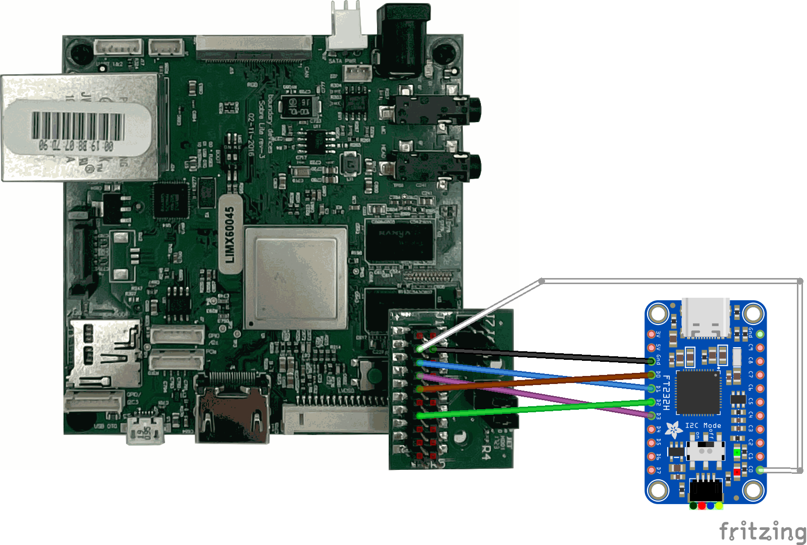
In the following, an exemplary setup is presented which allows JTAG debugging on the BD-SL-i.MX6 board using an Adafruit FT232H board. Please refer to the Runtime Debugging section to get an overview on debugging TRENTOS systems and the required tools. This chapter only provides the debugging details specific to the BD-SL-i.MX6 platform.
Nit6X_JTAG Adapter
For JTAG, the boards use a 10 pin (2x5, 1.27 mm pitch) connector. BoundaryDevices offers the “Nit6X_JTAG” adapter (https://boundarydevices.com/product/nit6x_jtag/), which provides the common 20 pin (2x10, 2.54 mm pitch) connector, that can easily be connected to the Adafruit FT232H board.
JTAG Pin Mapping
In order to properly connect the Nit6X_JTAG to the Adafruit FT232H, connect the following pins used for JTAG communication:
JTAG Signal |
Adafruit FT232H |
Cable Color |
Nit6X_JTAG Pin |
|---|---|---|---|
SRST (System Reset) |
- |
- |
- |
TRST (Test Reset) |
C0 |
white |
3 |
TCK (Test Clock) |
D0 |
brown |
9 |
TMS (Test Mode Select) |
D3 |
violet |
7 |
TDI (Test Data In) |
D1 |
blue |
5 |
TDO (Test Data Out) |
D2 |
green |
13 |
GND |
GND |
black |
4 |

OpenOCD Configuration File
As mentioned in the
Debugging HW Platforms Using OpenOCD
section, OpenOCD requires two different configuration files - one for the FT232H
board and one for the particular platform. The configuration file specific
to the BD-SL-i.MX6 platform is located in the same directory as the FT232H
configuration file (sdk/resources/openocd_cfgs/sabre.cfg).
Segger Toolchain Setup
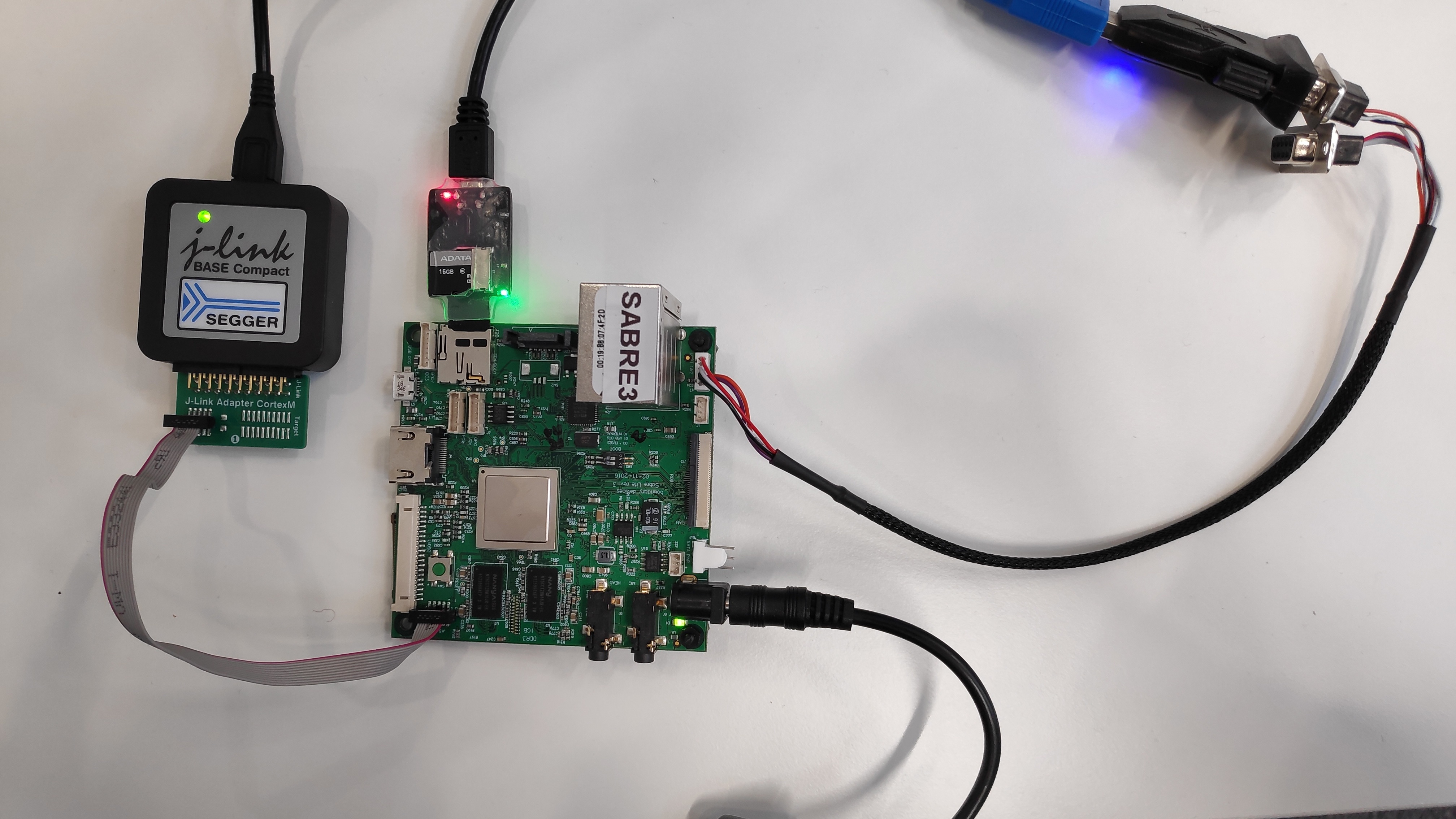
The HW setup of the BD-SL-i.MX6 platform for use with the Segger J-Link Base Compact is done as follows:
Connect the J-Link Adapter Cortex-M (https://www.segger.com/products/debug-probes/j-link/accessories/adapters/9-pin-cortex-m-adapter/) to the J-Link Base Compact (simple plug-in)
Connect the 10-pin connector from the Adapter Cortex-M adapter to the BD-SL-i.MX6 using the 10-pin cable (red cable marks the pin 1)
The HW setup is shown in the image below:

After the HW setup is completed, all other steps necessary to complete the setup of the BD-SL-i.MX6 platform for the use with the Segger toolchain are done as described in the Debugging HW Platforms Using Segger Tools section and no special steps are required.