RPi3B+ Debugging with JTAG
In the following, an exemplary setup is presented which allows JTAG
debugging on the RPi3B+. In order to connect to the RPi3B+ from the PC,
the two open-source tools OpenOCD and gdb are to be used. Please
refer to the Runtime Debugging
section to get an overview on debugging TRENTOS applications both on HW and in
QEMU. This chapter aims only to provide debugging details specific to
the RPi3B+ platform:
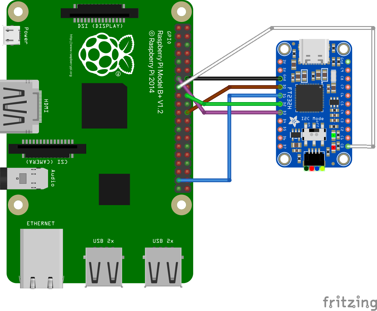
connection between the RPi3B+ board and the Adafruit FT232H board used as simple JTAG adapter
the RPi3B+ OpenOCD configuration
JTAG Pin Mapping
According to
https://www.raspberrypi.org/documentation/configuration/config-txt/gpio.md,
JTAG support needs to be enabled on the RPi3B+ via the config.txt file.
This has already been prepared in the file provided with the SDK.
enable_jtag_gpio=1
This selects the alternate mode ALT4 for some Broadcom SOC GPIOs, so the JTAG signals are routed and exposed at the 2x20 pin header. See also https://pinout.xyz/pinout/jtag about the pin mapping details. The table below gives an overview of the signals, the routing and where to connect the Adafruit FT232H board to the RPi3B+ to do JTAG debugging:
JTAG Signal |
Adafruit |
Cable color in the picture below |
RPi3B+ Pin on the 2x20 Pin Header |
Broadcom |
Notes |
|---|---|---|---|---|---|
TCK |
D0 |
brown |
22 |
25 |
JTAG spec recommends a pull-down resistor (4.7k - 10k) to avoid random clock signals if the pin is floating. The Adafruit FT232H board does not provide such a resistor, but debugging usually works without it, too. |
TMS |
D3 |
violet |
13 |
27 |
JTAG spec recommends a pull-up resistor (4.7k - 10k) to avoid having this pin floating. The Adafruit FT232H board does not provide such a resistor, but debugging usually works without it, too. |
TDI |
D1 |
blue |
37 |
26 |
JTAG spec recommends a pull-up resistor (4.7k - 10k) to avoid having this pin floating. The Adafruit FT232H board does not provide such a resistor, but debugging usually works without it, too. |
TDO |
D2 |
green |
18 |
24 |
JTAG adapter should use a 33R line resistor.The Adafruit FT232H board does not provide such a resistor, but debugging usually works without it, too. |
GND |
GND |
black |
14 |
- |
Ground |
TRST |
C0 |
white |
15 |
22 |
A pull-down resistor (4.7k - 10k) should be used to ensure the JTAG debug logic is disabled when unused. The Adafruit FT232H board does not provide such a resistor, but debugging usually works without it, too. |
SRST |
- |
- |
- |
- |
optional, unused |
RTCK |
- |
- |
16 |
23 |
optional, unused |
More details about the JTAG signals can be found in the IEEE Standard 1149.1 available at https://standards.ieee.org/standard/1149_1-2013.html and also at https://www2.lauterbach.com/pdf/app_arm_jtag.pdf. Raspberry Pi specific details can be found at https://metebalci.com/blog/bare-metal-raspberry-pi-3b-jtag.

OpenOCD Configuration File
As mentioned in the Debugging Applications on HW Platforms
section, OpenOCD requires two different configuration files - one
for the FT232H board and one regarding the particular platform. The
configuration file specific to the RPi3B+ platform is located in the
same directory as the FT232H configuration file
(sdk/resources/openocd_cfgs/rpi3.cfg).
Segger Toolchain Setup
As of now the RPi3B+ platform is not supported by the Segger toolchain:
Even though the newer versions of the probes support the Cortex-A53 (as
shown here:
https://wiki.segger.com/Software_and_Hardware_Features_Overview) on
which the Broadcom BCM2837 is based upon, the SoC itself is not
supported. Furthermore, Ozone does not allow for the selection of any
Cortex-A53 based platforms, and while the command tool JLinkGDBServer
does support some Cortex-A53 based SoCs from NXP, their settings do not
work for the RPi3B+ out of the box. In order to add support for RPi3B+,
it would be necessary to create a custom J-Link configuration script for
the board, which is not trivial. Documentation on writing the J-Link
script can be found on the Segger wiki here:
https://wiki.segger.com/J-Link_script_files.